Cory:
Unlock Your AI Assistant Now!
Abstract
Background: Coronary obstruction (CO) is a major concern in redo-transcatheter aortic valve implantation (TAVI) for failing supra-annular self-expanding transcatheter aortic valves (TAVs).
Aims: This ex vivo study tested chimney stenting (ChS) for redo-TAVI in patients with high-risk anatomy for CO by evaluating stent outcomes and the feasibility of subsequent coronary access (CA) for percutaneous coronary intervention (PCI).
Methods: Patient-specific anatomical models were three-dimensionally printed from pre-TAVI computed tomography (CT) scans. Index TAVI was performed using ACURATE neo2 (ACn2) or Evolut PRO (EvPRO) with varying degrees of commissural misalignment (CMA). Redo-TAVI with bilateral ChS was performed in a pulsatile flow simulator using the balloon-expandable SAPIEN 3 Ultra (S3U) at different implant depths. Stent expansion was measured by intravascular ultrasound. Stent interactions and distortion angles were assessed by micro-CT. CA for PCI was attempted subsequently.
Results: In the tested redo-TAVI combinations, interactions with index TAV frames or the aortic wall caused chimney stent distortion and underexpansion. A high S3U implant within an EvPRO resulted in the greatest stent underexpansion (complete crush) and vertical distortion (up to 75°). Severe CMA of the index TAV resulted in the greatest lateral stent distortion (up to 41° for ACn2 and 53° for EvPRO). The combination of CMA of the index TAV and a high S3U implant rendered CA and PCI after ChS unfeasible in 75% of cases.
Conclusions: ChS during redo-TAVI with the S3U within a degenerated ACn2 or EvPRO valve is susceptible to interactions between the coronary stent and the TAV frames or the aortic wall, leading to stent distortion and underexpansion, which might compromise procedural efficacy and future CA.
Transcatheter aortic valve implantation (TAVI) is expanding to younger patients with a long life expectancy, who are likely to outlive their implanted transcatheter aortic valve (TAV)12. Therefore, the need for redo-TAVI procedures is estimated to grow in the next years3. Redo-TAVI poses specific technical challenges, and prior studies have demonstrated that it may be unfeasible in a significant proportion of patients due to the risk of coronary obstruction (CO) related to the neoskirt created by the pinned leaflets of the index TAV, particularly in cases of degenerated supra-annular self-expanding platforms4.
Different coronary protection strategies have been proposed to overcome this issue and improve the feasibility of redo-TAVI. Leaflet modification by means of electrosurgical techniques or dedicated devices is one approach, which consists of cutting the leaflets of the index TAV to create an opening in the neoskirt567. However, current data on its efficacy in the setting of redo-TAVI are limited, and specific issues including commissural misalignment (CMA) and the frame design of the index TAV (TAV-1) might reduce its efficacy89. Furthermore, restricted local resources and technical requirements limit its widespread adoption. Chimney stenting (ChS) is an alternative strategy, which consists of implanting coronary stents protruding into the aorta to preserve coronary perfusion10. This technique is readily available, comparatively easier to perform, and has been proven effective in reducing the risk of CO for TAVI in native aortic valves or in degenerated surgical bioprostheses11. However, its performance in the setting of redo-TAVI has not yet been systematically evaluated. Specifically, the presence of the TAV-1 and the interaction with the second TAV (TAV-2) might pose unique challenges to a ChS strategy. Therefore, the aim of this ex vivo bench study was to evaluate the performance of ChS in different redo-TAVI configurations with a supra-annular self-expanding valve as the index TAV and a balloon-expandable valve as the revalving TAV.
Methods
Study design
This investigator-initiated study was designed and executed using patient-specific bench testing to allow for the systematic assessment of ChS following different redo-TAVI configurations in the same high-risk anatomical scenario of CO, which would not be possible in real patients (Figure 1). This study involved bench testing using patient-specific anatomical models. No human or animal participants were involved, and therefore, ethical approval was not required.
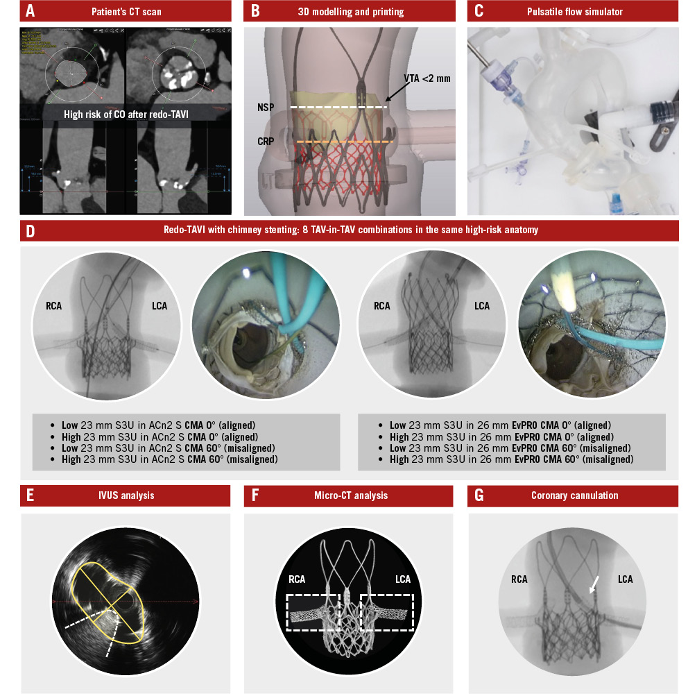
Figure 1. Study design and methodology. Identification of high-risk patient anatomy for CO after redo-TAVI using a CT scan (A), and 3D printing of a patient-specific anatomical model (B). Integration of the model into a pulsatile flow simulator (C) to perform redo-TAVI with ChS using multiple TAV-in-TAV combinations under real catheterisation laboratory conditions (D). IVUS (E) and micro-CT analysis (F) of stent outcomes, followed by testing for CA (G). 3D: three-dimensional; ACn2 S: ACURATE neo2 small; CA: coronary access; ChS: chimney stenting; CMA: commissural misalignment; CO: coronary obstruction; CRP: coronary risk plane; CT: computed tomography; EvPRO: Evolut PRO; IVUS: intravascular ultrasound; LCA: left coronary artery; NSP: neoskirt plane; RCA: right coronary artery; S3U: SAPIEN 3 Ultra; TAV: transcatheter aortic valve; TAVI: transcatheter aortic valve implantation; VTA: valve-to-aorta
Anatomical model
An ex vivo, three-dimensionally (3D)-printed, patient-specific, anatomical model was developed to simulate redo-TAVI with ChS. Patient anatomy was selected based on the high risk of CO due to sinus sequestration after redo-TAVI, as predicted by computed tomography (CT): (1) coronary ostia below the neoskirt plane (NSP), defined by the TAV-2 implant position within the TAV-1; and (2) a valve-to-aorta (VTA) distance <2 mm at the level of the NSP12. The original CT scan was electrocardiographically gated, contrast enhanced, and had a slice thickness <1 mm. Measurements of the native aortic root are reported in Supplementary Table 1. Raw data from the baseline pre-TAVI CT scan were exported in the Digital Imaging and Communications in Medicine (DICOM) format. The aorta, left ventricular blood pool, and left and right coronary arteries were segmented using semiautomatic segmentation algorithms with added manual corrections (3D Slicer software; https://www.slicer.org). The segmentations were converted into 3D mesh images, which were then converted into patient-specific 3D digital models. Polyjet technology was used to 3D print the models using a J720 3D printer (Stratasys). The 3D-printed model was assembled within a pulsatile flow circuit at physiological temperature and pressure to simulate real catheterisation laboratory conditions. The overall geometry of the pulsatile flow simulator was also derived from the patient’s CT, consisting of a full-length aorta, aortic arch, and iliofemoral axes, as previously described13.
TAV-1
ACURATE neo2 (ACn2; Boston Scientific) and Evolut PRO (EvPRO; Medtronic) supra-annular self-expanding valves were alternatively used as the degenerated TAV-1. Small (S) size ACn2 and 26 mm EvPRO were used, according to native annular dimensions. The implant depth of the TAV-1 was 7 mm for the ACn2 and 3 mm for the EvPRO, according to device manufacturer recommendations. Different degrees of TAV-1 CMA were tested for both platforms: commissural alignment (CMA 0°), and severe misalignment (CMA 60°), according to the ALIGN-TAVI definitions14.
TAV-2
SAPIEN 3 Ultra (S3U; Edwards Lifesciences) intra-annular balloon-expandable valves were used as the TAV-2 for redo-TAVI. The 23 mm S3U was selected, according to in vitro sizing recommendations for redo-TAVI1516. Two different TAV-2 implant positions were tested. The S3U outflow was alternatively aligned to the plane of the upper crowns (low implant) or to the base of the commissural posts (high implant) of the index ACn2, or to node 4 (low implant) or node 6 (high implant) of the index EvPRO, in low and high TAV-2 implants, respectively1516. All S3U valves were deployed with nominal volume as per manufacturer recommendations.
Chimney stenting procedure
Prior to the TAV-2 implant, a 0.014” coronary wire and a 4.0x24 mm SYNERGY MEGATRON (Boston Scientific) high radial force drug-eluting stent were delivered to each coronary artery through the optimal accessible cell of the TAV-1 stent frame, defined as the closest and the most coaxial cell to the coronary ostium. Advanced coronary access (CA) techniques, consisting of the fishing wire technique and the use of guide extension catheters, were allowed in case of CMA to facilitate stent delivery. Guide extension catheters were routinely used to protect the stents from interaction with the TAV frames during delivery and positioning. The stents were implanted with their proximal segment (stent snorkel inflow) above the top of the TAV-2 frame outflow. During TAV-2 implantation, both stent balloons remained inflated (triple kissing balloon inflation). Following TAV-2 balloon deflation, both stent balloons were used for post-dilatation to maximise stent expansion. The procedures were performed under fluoroscopic guidance, with the aid of an internally mounted borescope camera providing a top-down axial view of the aorta.
TESTED redo-TAVI configurations
The following 8 redo-TAVI configurations with ChS of both coronary arteries were tested in the anatomical model (Supplementary Figure 1):
• S3U low (upper crowns) in ACn2 CMA 0° (aligned)
• S3U high (commissural posts) in ACn2 CMA 0° (aligned)
• S3U low (upper crowns) in ACn2 CMA 60° (misaligned)
• S3U high (commissural posts) in ACn2 CMA 60° (misaligned)
• S3U low (node 4) in EvPRO CMA 0° (aligned)
• S3U high (node 6) in EvPRO CMA 0° (aligned)
• S3U low (node 4) in EvPRO CMA 60° (misaligned)
• S3U high (node 6) in EvPRO CMA 60° (misaligned)
Assessment of chimney stents
After each redo-TAVI procedure, the guide extension catheters and the coronary wires used to deliver the stents were left in place to facilitate delivery of the OPTICROSS HD intravascular ultrasound (IVUS) catheter (Boston Scientific) into each stented coronary artery. IVUS was used to evaluate the interactions of the chimney stents with the TAV frames from an internal perspective and to measure the maximal and minimal stent diameters and minimal stent area (MSA). Stent expansion was calculated as the percentage ratio of the measured MSA to the distal reference lumen area17. For the snorkel portion of the stent, the proximal left main body was used as the distal reference. Stent expansion was considered optimal if the MSA was >90% of the distal reference lumen area18. Micro-CT was performed for each redo-TAVI configuration tested in the study. All images were obtained using the Nikon XT H 225 ST 2x microfocus X-ray CT system (Nikon Metrology). Three-dimensional reconstructions of the micro-CT images were obtained using the Mimics Viewer (Materialise). Micro-CT reconstructions were used to qualitatively and quantitatively assess the interactions between chimney stents and TAV frames. The distortion of the stents was evaluated both on the frontal plane (vertical distortion) and on the axial plane (lateral distortion). The stent distortion angle (SDA) was calculated as the angle (<180°) between the body of the stent inside the coronary artery and its snorkel segment protruding into the aorta. The greater the angle, the greater the distortion on that plane.
Coronary cannulation procedures
After micro-CT analysis, CA and delivery of percutaneous coronary intervention (PCI) equipment (balloon and stent) were attempted in the pulsatile flow model by an experienced operator under fluoroscopic guidance in each redo-TAVI configuration. Cannulations were performed from the femoral access route. The operator was allowed to choose among a prespecified set of different 6 Fr guiding catheters (Judkins Left [JL]4, JL5, Amplatz Left [AL]1, extra back-up [EBU], multipurpose A [MPA] for the left coronary artery, and Judkins Right [JR]4, AL1, AL2, internal mammary [IM], MPA for the right coronary artery) and to use advanced CA techniques consisting of the fishing wire technique (using workhorse or hydrophilic wires), the use of guide extension catheters, and balloons for anchoring or chimney stent dilatation. Primarily, end-on cannulation of the neo-ostium was attempted, followed by side-on cannulation through the stent struts as bailout, as previously described19. An internally mounted borescope camera was used to directly visualise the catheters and their interactions with chimney stents from a top-down axial view. The operator was blinded to the borescope camera.
Statistical analysis
The SDA measurements are expressed in degrees (°). The MSA measurements are expressed in square millimetres (mm²). Stent expansion is expressed as a percentage (%) of the distal reference lumen area.
Results
Interactions between chimney stents and TAV frames
An overview of the observed interactions is illustrated in Supplementary Figure 2. The portion of the chimney stent entering the TAV-1 accessible open cell was at risk of major interaction with the TAV frames. For the S3U-in-ACn2 combinations, chimney stents interacted with the upper crowns or the commissural posts of the ACn2 frame and with the outside of the S3U frame, resulting in stent displacement and compression between the S3U frame and the aortic wall. The worst interactions and subsequent stent distortion were observed in the case of a high S3U implant inside a misaligned ACn2 (Figure 2). For the S3U-in-EvPRO combinations, chimney stents interacted with the cell edges or the commissural posts of the EvPRO frame and with the outside of the S3U frame, resulting in stent crush between the two TAVs. The worst interactions were observed in the case of a high S3U implant inside a misaligned EvPRO, resulting in greater distortion and crush of a longer segment of the stent (Figure 3).
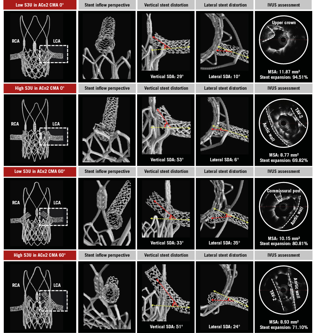
Figure 2. Chimney stenting for ACn2. Detailed assessment of chimney stents across different redo-TAVI configurations for a degenerated ACn2. The LCA stent (dashed box) is evaluated. ACn2: ACURATE neo2; CMA: commissural misalignment; IVUS: intravascular ultrasound; LCA: left coronary artery; MSA: minimal stent area; RCA: right coronary artery; S3U: SAPIEN 3 Ultra; SDA: stent distortion angle; TAV-2: second TAV; TAV: transcatheter aortic valve; TAVI: transcatheter aortic valve implantation
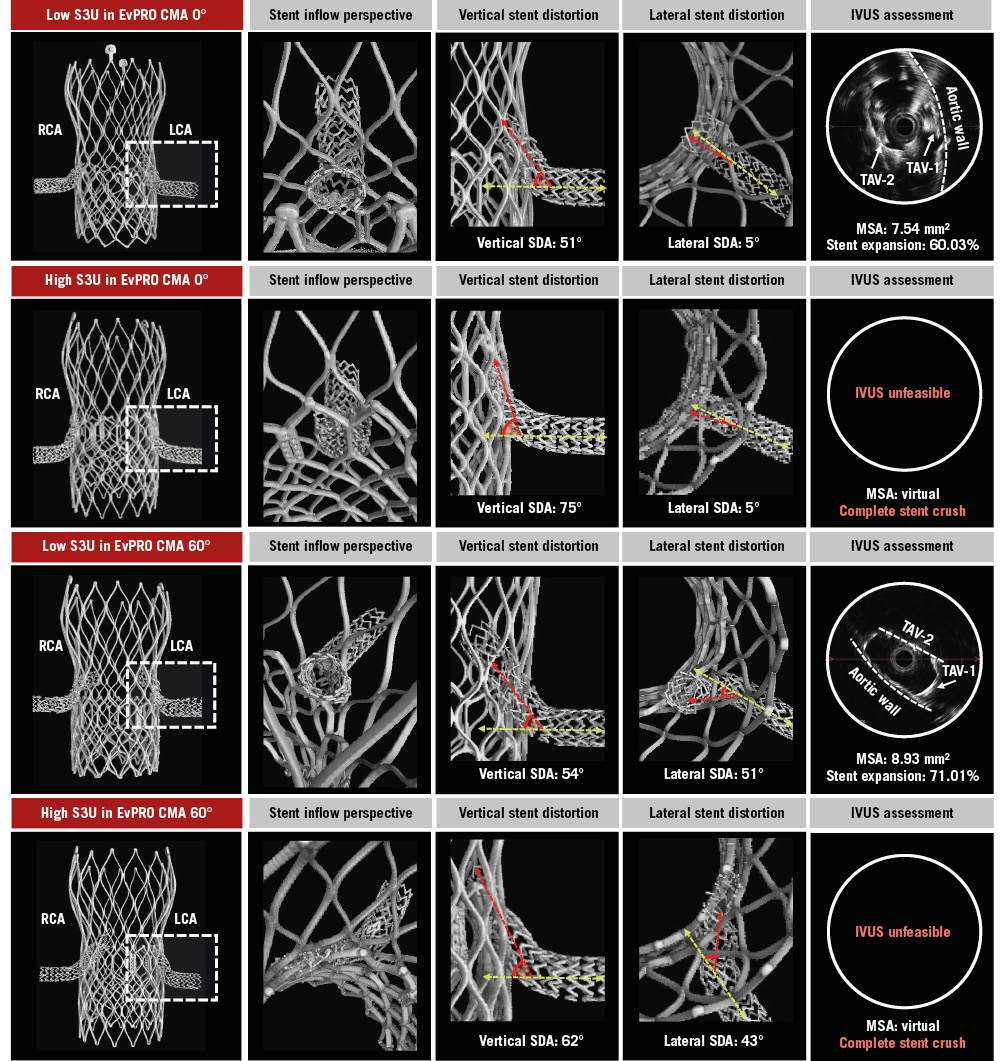
Figure 3. Chimney stenting for EvPRO. Detailed assessment of chimney stents across different redo-TAVI configurations for a degenerated EvPRO. The LCA stent (dashed box) is evaluated. CMA: commissural misalignment; EvPRO: Evolut PRO; IVUS: intravascular ultrasound; LCA: left coronary artery; MSA: minimal stent area; RCA: right coronary artery; S3U: SAPIEN 3 Ultra; SDA: stent distortion angle; TAV-1: index TAV; TAV-2: second TAV; TAV: transcatheter aortic valve; TAVI: transcatheter aortic valve implantation
Chimney stent distortion
The degree of vertical and lateral distortion of the chimney stent varied according to the specific TAV-in-TAV combination. The design of the index TAV as well as the S3U implant depth impacted vertical stent distortion, whilst the degree of TAV-1 CMA increased lateral stent distortion. In the case of a low S3U implant, the vertical SDA ranged from 29° to 35° for the ACn2 and from 48° to 58° for the EvPRO. A high S3U implant increased the vertical SDA up to 53° for the ACn2 and up to 75° for the EvPRO. In the case of an aligned TAV-1, the lateral stent SDA ranged from 6° to 15° for the ACn2 and from 3° to 10° for the EvPRO. Severe TAV-1 CMA increased the lateral SDA up to 41° for the ACn2 and up to 53° for the EvPRO (Table 1).
Table 1. Chimney stent distortion.
| TAV-1 | TAV-1 CMA, ° | TAV-2 | TAV-2 implant depth | Coronary artery | Vertical SDA, ° | Lateral SDA, ° |
|---|---|---|---|---|---|---|
| ACn2 size S | 0 (aligned) | S3U 23 mm | Low (upper crown) | LCA | 29 | 10 |
| RCA | 32 | 15 | ||||
| High (commissural post) | LCA | 53 | 6 | |||
| RCA | 53 | 8 | ||||
| 60 (misaligned) | S3U 23 mm | Low (upper crown) | LCA | 33 | 35 | |
| RCA | 35 | 40 | ||||
| High (commissural post) | LCA | 51 | 24 | |||
| RCA | 50 | 41 | ||||
| EvPRO 26 mm | 0 (aligned) | S3U 23 mm | Low (node 4) | LCA | 51 | 5 |
| RCA | 48 | 3 | ||||
| High (node 6) | LCA | 75 | 5 | |||
| RCA | 68 | 10 | ||||
| 60 (misaligned) | S3U 23 mm | Low (node 4) | LCA | 54 | 51 | |
| RCA | 52 | 53 | ||||
| High (node 6) | LCA | 62 | 43 | |||
| RCA | 44 | 41 | ||||
| ACn2: ACURATE neo2; CMA: commissural alignment; EvPRO: Evolut PRO; LCA: left coronary artery; RCA: right coronary artery; S: small; S3U: SAPIEN 3 Ultra; SDA: stent distortion angle; TAV-1: index TAV; TAV-2: second TAV; TAV: transcatheter aortic valve | ||||||
Chimney stent expansion
The degree of chimney stent expansion was affected by the specific TAV-in-TAV combination. Across all configurations, the chimney stents were underexpanded and elliptically shaped in their proximal segment. The implant depth of the S3U had the greatest impact on chimney stent expansion. In the case of a high S3U inside an EvPRO, the stents were completely crushed between the TAV frames, making it unfeasible to advance an IVUS catheter to obtain MSA measurements. Similarly, a high S3U implant inside an ACn2 resulted in the smallest MSA achieved amongst the ACn2 combinations (Table 2). Lowering the S3U implant depth improved the chimney stent expansion, with the largest MSA of 11.87 mm2 (94.51% stent expansion) observed in the case of a low S3U implant inside an ACn2, and the smallest MSA of 7.54 mm2 (60.03% stent expansion) observed in the case of a low S3U implant inside an EvPRO.
Table 2. Chimney stent expansion.
| TAV-1 | TAV-1 CMA, ° | TAV-2 | TAV-2 implant depth | Coronary artery | Max D, mm | Min D, mm | MSA, mm2 | Expansion, % |
|---|---|---|---|---|---|---|---|---|
| ACn2 size S | 0 (aligned) | S3U 23 mm | Low (upper crown) | LCA | 4 | 3.74 | 11.87 | 94.51 |
| RCA | 4.01 | 3.6 | 11.09 | 88.3 | ||||
| High (commissural post) | LCA | 4.41 | 2.69 | 8.77 | 69.82 | |||
| RCA | 4.58 | 2.28 | 9.58 | 76.27 | ||||
| 60 (misaligned) | S3U 23 mm | Low (upper crown) | LCA | 4.03 | 3.11 | 10.15 | 80.81 | |
| RCA | 4.25 | 3.14 | 10.55 | 84 | ||||
| High (commissural post) | LCA | 5.11 | 1.61 | 9.62 | 76.59 | |||
| RCA | 4.33 | 2.3 | 8.97 | 71.42 | ||||
| EvPRO 26 mm | 0 (aligned) | S3U 23 mm | Low (node 4) | LCA | 4.55 | 1.71 | 7.54 | 60.03 |
| RCA | 4.41 | 2.99 | 10.96 | 87.26 | ||||
| High (node 6) | LCA | * | * | * | * | |||
| RCA | * | * | * | * | ||||
| 60 (misaligned) | S3U 23 mm | Low (node 4) | LCA | 4.56 | 2.37 | 8.93 | 71.1 | |
| RCA | 4.4 | 2.83 | 9.09 | 72.37 | ||||
| High (node 6) | LCA | * | * | * | * | |||
| RCA | * | * | * | * | ||||
| *IVUS unfeasible due to complete stent crush between the two TAV frames. ACn2: ACURATE neo2; CMA: commissural alignment; D: diameter; EvPRO: Evolut PRO; IVUS: intravascular ultrasound; LCA: left coronary artery; MSA: minimal stent area; RCA: right coronary artery; S3U: SAPIEN 3 Ultra; TAV-1: index TAV; TAV-2: second TAV; TAV: transcatheter aortic valvet | ||||||||
Coronary access after chimney stenting
Overall, 16 coronary cannulations were attempted in the 8 redo-TAVI configurations. CA and PCI equipment delivery through chimney stents were unfeasible in 75% (12/16) of cases due to the combination of stent distortion on multiple planes and stent compression. The only TAV-in-TAV combinations which facilitated CA and PCI equipment delivery after ChS were those with a low S3U implant inside an aligned index TAV. In these cases, advanced CA techniques were required: end-on CA was achieved for both coronary arteries using AL1 or EBU 3.0 guiding catheters, approaching the stent snorkel from above and using a 0.035” wire to modify the curve of the guiding catheter. Wiring of the chimney stents was performed with a 0.014” wire using the fishing technique and advancing through the stent lumen with a loop. High-pressure ballooning of the chimney stents was necessary to advance guide extension catheters and deliver PCI equipment to both coronary arteries in the case of an EvPRO as the index TAV (Table 3, Figure 4).
Table 3. Coronary access after redo-TAVI with chimney stenting.
| TAV-1 | TAV-1 CMA, ° | TAV-2 | TAV-2 implant depth | Coronary artery | CA | GC | Advanced CA technique |
|---|---|---|---|---|---|---|---|
| ACn2 size S | 0 (aligned) | S3U 23 mm | Low (upper crown) | LCA | EBU 3.0 | Fishing wire, GEC | |
| RCA | AL1 | Fishing wire, GEC | |||||
| High (commissural post) | LCA | - | Unfeasible | ||||
| RCA | - | Unfeasible | |||||
| 60 (misaligned) | S3U 23 mm | Low (upper crown) | LCA | - | Unfeasible | ||
| RCA | - | Unfeasible | |||||
| High (commissural post) | LCA | - | Unfeasible | ||||
| RCA | - | Unfeasible | |||||
| EvPRO 26 mm | 0 (aligned) | S3U 23 mm | Low (node 4) | LCA | EBU 3.0 | Fishing wire, GEC, predilatation | |
| RCA | AL1 | Fishing wire, GEC, predilatation | |||||
| High (node 6) | LCA | - | Unfeasible | ||||
| RCA | - | Unfeasible | |||||
| 60 (misaligned) | S3U 23 mm | Low (node 4) | LCA | - | Unfeasible | ||
| RCA | - | Unfeasible | |||||
| High (node 6) | LCA | - | Unfeasible | ||||
| RCA | - | Unfeasible | |||||
| ACn2: ACURATE neo2; AL: Amplatz Left; CA: coronary access; CMA: commissural misalignment; EBU: extra back-up; EvPRO: Evolut PRO; GC: guiding catheter; GEC: guide extension catheter; LCA: left coronary artery; RCA: right coronary artery; S: small; S3U: SAPIEN 3 Ultra; TAV-1: index TAV; TAV-2: second TAV; TAV: transcatheter aortic valve | |||||||
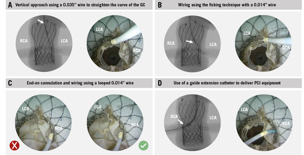
Figure 4. Coronary access after redo-TAVI with chimney stenting: advanced techniques. Overview of the advanced techniques used to obtain CA and deliver PCI equipment through chimney stents. A) Vertical approach; (B) the fishing technique; (C) end-on cannulation; (D) use of a guide extension catheter to deliver PCI equipment. CA: coronary access; GC: guiding catheter; LCA: left coronary artery; PCI: percutaneous coronary intervention; RCA: right coronary artery; TAVI: transcatheter aortic valve implantation
Discussion
This study provides a detailed assessment of the specific interactions affecting chimney stents in redo-TAVI (Central illustration). The use of an ex vivo patient-specific simulator is unique and provides anatomical context to this bench study, allowing for a direct comparison of ChS performance across a wide range of TAV-in-TAV combinations within the same high-risk scenario, which is impossible in vivo. The main findings of this study can be summarised as follows: (1) interactions between chimney stents and TAV frames or the aortic wall can cause significant stent distortion and underexpansion; (2) the design of the index TAV impacts chimney stent outcomes, with stent expansion and distortion being overall worse for the closed-frame EvPRO; (3) the greater the degree of CMA of the index TAV, the greater the lateral chimney stent distortion; (4) a high S3U implant has the most detrimental effect on chimney stent expansion and distortion; and (5) the combination of chimney stent distortion and underexpansion impairs CA and PCI equipment delivery.
Previous studies have shown that ChS is an option for coronary protection in TAVI procedures at high risk of CO, typically in the TAV-in-surgical bioprosthesis scenario1011. However, applying ChS to the setting of redo-TAVI calls for specific considerations regarding feasibility, efficacy, and future CA. Operators should be aware that chimney stent distortion combined with underexpansion might jeopardise the result of the procedure, increase the risk of stent thrombosis, and compromise future CA. Therefore, attention should be focused on optimising the index TAV implant and, when dealing with a previously implanted TAV at high risk for CO, planning a redo-TAVI strategy that allows for an optimal ChS outcome.
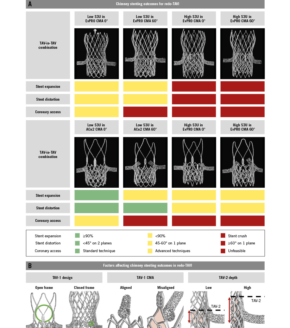
Central illustration. Chimney stenting for redo-TAVI with a balloon-expandable valve within degenerated supra-annular self-expanding platforms. A) Chimney stenting outcomes for redo-TAVI. B) Factors affecting chimney stenting outcomes for redo-TAVI. ACn2: ACURATE neo2; CMA: commissural misalignment; EvPRO: Evolut PRO; S3U: SAPIEN 3 Ultra; TAV-1: index TAV; TAV-2: second TAV; TAV: transcatheter aortic valve; TAVI: transcatheter aortic valve implantation
Impact of index TAV on chimney stenting
Optimising the index TAV implant is an important first step in achieving successful transcatheter lifetime management of aortic stenosis, especially in high-risk anatomies requiring coronary protection strategies to preserve coronary flow and CA after redo-TAVI. The design and the degree of CMA of the index TAV affect both the feasibility and outcomes of ChS in this setting.
ChS for redo-TAVI generally requires coronary cannulation and stent delivery through the open cell of the TAV-1 frame. Different TAV platforms vary in the size and shape of the accessible open cell, which can affect CA. A previous bench study using micro-CT analysis showed that the area of the fully open cell of the EvPRO frame is 16-20 mm2 for the 23-29 mm EvPRO valves. The ACn2 features a different design with only 3 stabilisation arches above the level of the upper crowns instead of a closed frame, providing a larger accessible cell area of 490-610 mm2 for the 23-27 mm ACn2 valves20. Additionally, data from the ALIGN ACCESS study demonstrated that CMA is an independent predictor of impaired CA after TAVI with supra-annular self-expanding platforms, leading to unfeasibility in up to 11% of cases21.
Overall, stent expansion and distortion are worse in combinations involving the EvPRO and are negatively affected by CMA of the index TAV. The edges of the accessible cell interact with the stent, and the closed frame of the EvPRO acts as a single external surface against which the stent might be crushed by the S3U frame. Conversely, the open-frame design of the ACn2 eliminates this risk but still exposes the stents to interaction with the upper crowns and to potentially being crushed between the S3U frame and the aortic wall.
A high degree of CMA of the index TAV increases stent distortion due to the interaction with the commissural posts. The lateral deviation of the stent snorkel increases the extent of the interaction with TAV frames or with the aortic wall. Finally, in the case of effaced sinuses, the segment of the snorkel external to the EvPRO frame might be crushed against the aortic wall due to the outward expansion of the frame created by the S3U implant1516.
Optimising chimney stenting for redo-TAVI
When planning a redo-TAVI procedure with ChS coronary protection, careful consideration should be given to the implant depth of the S3U to optimise stent outcomes. To effectively prevent CO, chimney stents should extend above the level of the neoskirt. The implant position of the short-frame S3U inside a tall-frame index TAV defines the neoskirt height in this TAV-in-TAV combination. Consequently, a higher implant position of the S3U increases the length of the chimney stent snorkel exposed to the risk of being crushed between TAV frames or against the aortic wall. Therefore, when considered feasible, a lower S3U implant position should be preferred to minimise this “stent danger zone” and reduce the likelihood of chimney stent distortion and underexpansion.
Several technical refinements have been proposed to optimise chimney stent expansion in the setting of redo-TAVI, encompassing the use of coronary stents with high radial force, double stent layers, triple kissing balloon inflation (simultaneous inflation of a TAV balloon and stent balloons), and high-atmosphere post-dilatation. In this study, the combined use of stents with high radial force, triple kissing balloon and high-atmosphere post-dilatation was not sufficient to prevent chimney stent distortion and crush. Excluding the cases of complete stent crush, the observed stent expansion ranged from 60% to 72% in the case of EvPRO as the TAV-1, and from 69% to 94% in the case of ACn2 as the TAV-1, resulting in most cases below the threshold of >90%, which has been associated with improved hard clinical outcomes in studies on IVUS-guided percutaneous coronary intervention18.
Coronary access after chimney stenting
Future CA feasibility is a key aspect to consider when evaluating a coronary protection strategy. Coronary cannulation, wiring, and PCI equipment delivery through chimney stents might be challenging or even impossible because of the combination of stent distortion on multiple planes and underexpansion. Furthermore, chimney stents might get damaged during the attempt. When end-on cannulation of the neo-ostium is impossible, side-on cannulation and wiring through the stent struts could be considered as a bailout option. However, this approach requires crushing of the initial stent and implanting a second chimney stent, which raises concerns about its reproducibility and long-term outcomes19. In this study, even with the use of advanced CA techniques, end-on cannulation and PCI equipment delivery after ChS were achieved only in 25% of cases where a low S3U implant was used inside an aligned index TAV. In contrast, leaflet modification techniques appear to be more favourable in terms of preserving CA13.
Limitations
This study relies on patient-specific bench testing to test different redo-TAVI combinations in the same anatomy. All the tests were performed in high-risk anatomies for CO and may not represent the regular redo-TAVI scenario. Despite its robustness, the model might not fully replicate the complexity of in vivo procedures in a real catheterisation laboratory setting, potentially affecting the generalisability of the study findings. The feasibility of ChS obtained in vivo might differ from that obtained in the present study, particularly in case of severe TAV-1 CMA. Indeed, while equipment and techniques were the same, ex vivo ChS was performed with the aid of an internal borescope camera to allow precise access through the optimal accessible cell of the TAV-1 frame, and with the unrestricted use of advanced CA techniques. The lack of a specific ex vivo methodology to assess coronary perfusion limits the assessment of the efficacy of ChS on coronary perfusion. Furthermore, the study was conducted using pristine TAVs, potentially underestimating the negative impact of heavily degenerated and calcified leaflets on stent deformation. Additionally, all the procedures were performed using a nominal implant depth of the TAV-1 for all the tested configurations. Although an intentionally high implant of the second TAV in the setting of high risk of CO is not clinically advisable, the use of patient-specific bench testing allowed for testing this worst-case scenario. Finally, the study’s ex vivo nature precludes the collection of longitudinal clinical data, limiting the ability to assess the long-term implications of ChS on patient outcomes over time.
Conclusions
In the setting of redo-TAVI with a balloon-expandable valve to treat a degenerated supra-annular self-expanding platform, a coronary protection strategy of ChS is affected by the interactions between coronary stents and TAV frames or the aortic wall, potentially leading to stent distortion and underexpansion. This might compromise the efficacy of the procedure and future CA. Further clinical studies are warranted to clarify the role of ChS in redo-TAVI.
Impact on daily practice
Redo-transcatheter aortic valve (TAV) implantation with a balloon-expandable valve to treat a degenerated supra-annular self-expanding valve might carry the risk of coronary obstruction in a considerable proportion of patients. Different coronary protection strategies have been proposed to overcome this issue. In this setting, the efficacy of chimney stenting (ChS) and future coronary access might be compromised by interactions between the coronary stent and the TAV frames or the aortic wall, leading to stent distortion and underexpansion. A closed-frame design of the index TAV and a high implant position of the second TAV carry the highest risk of negative stent outcomes. Therefore, the use of ChS should be carefully evaluated against alternative coronary protection strategies in TAV-in-TAV combinations with the highest risk of adverse stent outcomes. Further in vivo studies are needed to validate these findings.
Acknowledgements
Chris Frawley, BEng, Daire Grant, BEng, Lisa Lynch, MSc, and Conor White, BEng, from the Boston Scientific Galway Simulation Laboratory (Galway, Ireland) provided facilities and support necessary for the completion of this study.
Funding
This study was supported by an investigator-sponsored research grant from Boston Scientific. Boston Scientific provided equipment but was not involved in the design, planning or execution of the study.
Conflict of interest statement
A. Beneduce received speaker fees from Abiomed, Boston Scientific, and Medtronic. A.A. Khokhar received speaker fees from Boston Scientific. F. Giannini received speaker fees from Boston Scientific. W.-K. Kim is a proctor for Boston Scientific, Abbott, and Meril Life Sciences; received speaker fees from Boston Scientific, Abbott, Edwards Lifesciences, Meril Life Sciences, and Shockwave Medical; is an advisory board member to Boston Scientific and HID; and received institutional fees from Boston Scientific. F. Maisano received grants and/or institutional research support from Abbott, Medtronic, Edwards Lifesciences, Biotronik, Boston Scientific, NVT, and Terumo; consulting fees, personal and institutional honoraria from Abbott, Medtronic, Edwards Lifesciences, Xeltis, and Cardiovalve; royalty income/IP rights from Edwards Lifesciences; and is a shareholder (including share options) of CardioGard, Magenta, SwissVortex, Transseptal Solutions, Occlufit, 4Tech, and Perifect. O. De Backer received institutional research grants and consulting fees from Boston Scientific. D. Dudek is a scientific advisory board member of Boston Scientific. The other authors report no conflicts of interest.
Supplementary data
To read the full content of this article, please download the PDF.