Cory:
Unlock Your AI Assistant Now!
Abstract
Recurrent tricuspid valve regurgitation (TVR) after tricuspid transcatheter edge-to-edge repair (T-TEER) poses a significant challenge, particularly when centrally positioned clips impede subsequent transcatheter tricuspid valve replacement (TTVR). Electrosurgical laceration and stabilisation of T-TEER (ELASTA-T) has been developed to facilitate TTVR by enabling controlled single leaflet device attachment (SLDA). The aim of this manuscript is to provide a step-by-step standardised description of the ELASTA-T strategy, outlining essential procedural principles, the required equipment, and technical steps. ELASTA-T involves intentional detachment of the most centrally placed tricuspid clip using electrosurgical leaflet laceration. A modified coronary guidewire shaped into a “flying V” – based on Bioprosthetic Aortic Scallop Intentional Laceration to prevent Iatrogenic Coronary Artery obstruction (BASILICA) and Laceration of the Anterior Mitral leaflet to Prevent Outflow ObstructioN (LAMPOON) principles – is positioned across the target leaflet using bilateral femoral vein access, deflectable guiding sheaths, microcatheters, and a snare-assisted venovenous rail. Laceration is performed under fluoroscopic and transoesophageal echocardiographic guidance, with preventive haemodynamic support on standby because of the risk of transient severe TVR. After laceration, the clip is mobilised towards the septal leaflet to avoid interference with valve deployment, followed by immediate implantation of a dedicated transcatheter tricuspid valve (TTV). ELASTA-T allows safe and reproducible SLDA, creating adequate central space for accurate positioning and full expansion of a TTV. Detachment can be reliably confirmed by fluoroscopy and transoesophageal echocardiography. By removing any mechanical obstruction from centrally placed clips, the technique facilitates secure TTVR anchoring and may reduce paravalvular regurgitation. This step-by-step framework may support procedural standardisation and broader adoption, ultimately improving outcomes in this high-risk population.
Tricuspid valve regurgitation (TVR) is associated with increased morbidity and mortality when left untreated1. Transcatheter tricuspid interventions have recently demonstrated the ability to reduce TVR and improve health status, with multiple techniques emerging as therapeutic options234. Among these, tricuspid transcatheter edge-to-edge repair (T-TEER) showed improved quality of life compared with optimal medical therapy (OMT) in a randomised trial5.
Although T-TEER is commonly used as an adjunct to OMT, effective TVR reduction often requires multiple devices. While 1-year outcomes report successful TVR reduction in up to 81% of patients6, recurrent regurgitation remains a relevant limitation, occurring in 6.7% to 19% of cases67.
Reintervention via transcatheter tricuspid valve replacement (TTVR) offers a more effective solution, aiming for complete resolution of TVR8. Despite the anatomical challenges posed by T-TEER devices, which can impede proper TTVR implantation as well as increase the risks of technical failure and valve migration, the successful implantation of a dedicated transcatheter tricuspid valve (TTV) was recently reported9.
Electrosurgical laceration and stabilisation of T-TEER (ELASTA-T) has been proposed as a means to facilitate TTVR when T-TEER devices may hinder optimal implantation101112.
The objective of this manuscript is to provide a step-by-step standardised and integrated guide that consolidates the necessary tools and material coordination, along with providing a detailed procedural description.
Strategy behind ELASTA-T
The ELASTA-T procedure is designed to intentionally detach a transcatheter edge-to-edge repair (TEER) clip in the tricuspid position to allow subsequent implantation of a dedicated TTV in patients with recurrent tricuspid regurgitation and heart failure following TEER. Most TTVs require adequate central space for precise positioning, anchoring, and deployment3. In T-TEER, clips are typically placed at the anteroseptal commissure, with additional clips positioned parallel or at the posteroseptal commissure as needed, depending on regurgitant flow and anatomy. Commissural clips generally do not interfere with TTVR, whereas centrally placed clips may prevent correct prosthesis positioning. The selected clip(s) to be detached in the ELASTA-T procedure are consequently the most centrally positioned, depending on the number of implanted clips. The clip should be left attached to the septal leaflet and detached from the other leaflet (i.e., anterior or posterior, depending on which leaflets were originally clipped). Successful detachment can be confirmed by transoesophageal echocardiography (TOE), ensuring full valve expansion and minimising paravalvular regurgitation.
Because intentional electrical laceration and single leaflet device attachment (SLDA) may result in significant regurgitant flow of the tricuspid valve and consequently reduced forward flow with low cardiac output, standard preventive measures to counteract haemodynamic instability must be set up prior to performing this procedure. Most importantly, ELASTA-T is intended to be performed in the setting of concomitant TTVR (during the same procedure). It is advisable to prepare the dedicated TTV before the detachment step of the ELASTA-T procedure (Central illustration).
The principle of electrosurgery for the ELASTA-T procedure is the exact same as already introduced and described for other dedicated electrosurgery procedures such as Bioprosthetic Aortic Scallop Intentional Laceration to prevent Iatrogenic Coronary Artery obstruction (BASILICA)1314 and Laceration of the Anterior Mitral leaflet to Prevent Outflow ObstructioN (LAMPOON)1516. A “flying V” (Figure 1A-Figure 1B-Figure 1C-Figure 1D) is manually created from a stiff coronary 0.014” guidewire following selective denudation of the insulative coating on its inner surface. It is placed between two coronary guiding catheters to cut the leaflet tissue with electrosurgery, oriented towards the anterior or posterior commissure of the tricuspid valve. Mechanical avulsion of the leaflet tissue is avoided by electrical insulation of the “flying V” with the help of microcatheters and non-ionic dextrose flushing.
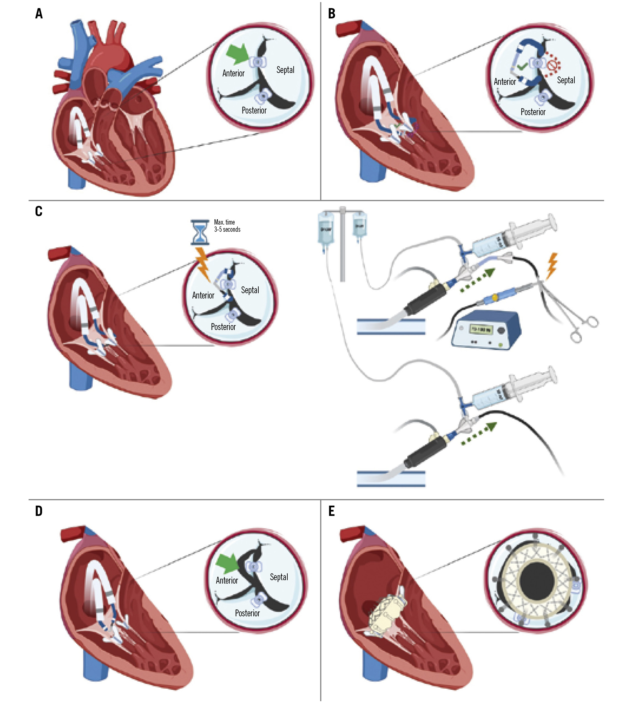
Central illustration. ELASTA-T: Electrosurgical laceration of tricuspid edge-to-edge repair. A) Diagram showing the tricuspid valve and the position of the clip to be detached (green arrow) grasping the anteroseptal leaflets, with a second clip attached only to the posterior leaflet; (B) “flying V” formed with an Astato wire positioned at the lateral side of the clip to be detached (anterior leaflet); (C) laceration of the leaflet using electrocautery settled at 70-100 W in “cut” mode for 3-5 seconds while pulling both catheters and flushing with dextrose simultaneously; (D) confirmation of the anterior leaflet laceration (green arrow); (E) final result after tricuspid valve implantation.
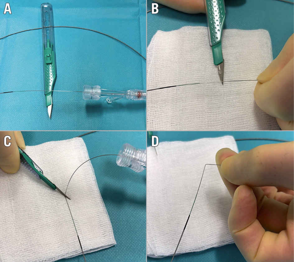
Figure 1. “Flying V” formation. A) Exposing a segment of the guidewire for denudation; (B) denuding a segment of the guidewire using the sharp side of the scalpel blade; (C) bending the denuded segment of the guidewire using the back side of the scalpel blade; (D) denuded segment forming the “flying V”.
Material needed
1x suture-based vascular closure device (optional)
1x Judkins Right (JR)- or internal mammary (IM)-shaped guiding 7 Fr catheter
1x multipurpose guiding 7 Fr catheter
2x deflectable guiding sheaths, each 61-82 cm in length and with an inner diameter matching the guiding catheter, such as an Agilis NxT 8.5 Fr medium (22.4 mm) or large (50 mm) Curl (Abbott), depending on cardiac dimensions
1x balloon-wedge endhole catheter with a 0.035” lumen (e.g., a Swan-Ganz)
1x Amplatz GooseNeck (Medtronic) snare or trilobe snare, 20 mm in diameter
1x coronary microcatheter, 130 cm in length (e.g., FineCross MG [Terumo]).
1x Asahi Astato XS 20 0.014”, 300 cm coronary wire (Asahi Intecc)
1x standard exchange wire
1x electrosurgery pencil (caution: avoid models with coated or insulated tips, such as Valleylab Edge [Medtronic], because the insulation prevents electrical connection to the generator)
1x electrosurgery generator
Procedure guidance
Patient preparation and femoral access:
1. According to local standards, either provide general anaesthesia and TOE guidance or use moderate sedation and intracardiac echocardiographic (ICE) guidance.
2. Set up 2 femoral vein accesses (both sides).
3. If employing a suture-based vascular closure device, deploy one preclosure device (Perclose ProStyle or Perclose ProGlide [both Abbott]) at the main access (preferably the right side). Otherwise, the choice of vascular closure device – such as manual compression or Z-suture − is at the operator’s discretion.
4. Use the computed tomography scan provided for tricuspid valve evaluation to investigate the best projections to identify the clip device that needs to be detached (Supplementary Figure 1A). Investigate 2 C-arm angulations to compile a lateral (side) (Supplementary Figure 1B) and an en face projection (Supplementary Figure 1C) of the anatomical landmark (attached clip). Usually, a lateral (side) view is provided by a right anterior oblique (RAO) angulation and an en face view by a left anterior oblique (LAO)/cranial (CRA) angulation.
Tricuspid valve passage
5. Advance 2 61-82 cm, 8.5 Fr deflectable guiding sheaths into both femoral access sites (Figure 2A, Figure 2B). As an alternative, single-vein femoral access can be achieved by introducing a large-bore sheath, such as a GORE DRYSEAL Flex Introducer Sheath (W. L. Gore & Associates), when available.
6. Through one deflectable guiding sheath, insert a standard exchange wire and a balloon wedge catheter into the right atrium.
7. Inflate the balloon wedge catheter and deflect guiding sheath “A” to cross through the first orifice, “A”, alongside the clip(s) targeted for detachment, making sure not to entangle it with the subvalvular apparatus, including the chords and papillary muscles, and avoiding laceration close to the papillary muscles (Figure 2C, Figure 2D).
8. Using the second deflectable guiding sheath “B”, insert a standard exchange wire and a balloon wedge catheter (Figure 2E, Figure 2F).
9. Inflate the balloon wedge catheter and deflect guiding sheath “B” to cross through orifice “B” alongside the clip, making sure not to entangle it with the subvalvular apparatus, including the chords and papillary muscles (Figure 2G-Figure 2J). Confirm the position and free movement with TOE.
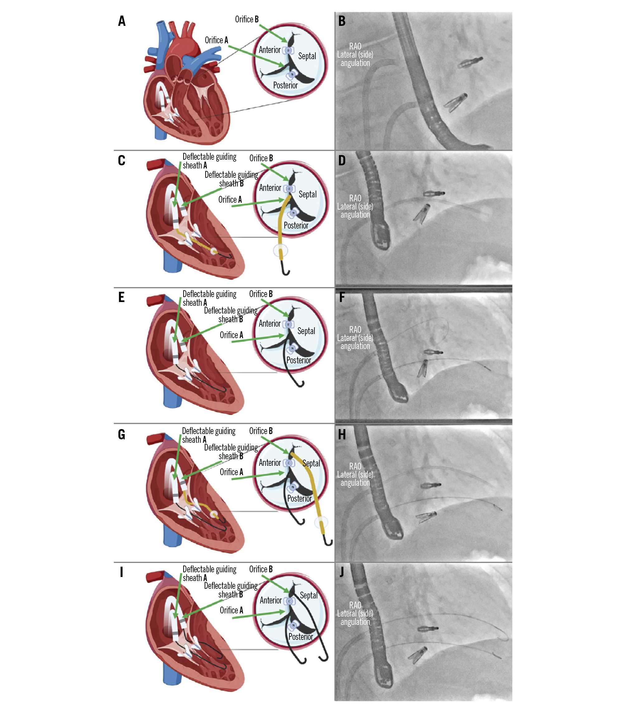
Figure 2. Tricuspid valve passage. A) Diagram of the tricuspid valve showing the target orifices for making the loop: orifice “B” (at the level of the anteroseptal commissure) and orifice “A” (between the septal and posterior leaflets); (B) angiographic view in the lateral (side) angulation showing 2 deflectable guiding sheaths in the working position and the 2 clips; (C) through the deflectable guiding sheath “A”, use a wedge catheter for crossing orifice “A”; (D) angiographic view in the lateral (side) angulation showing a wedge catheter crossing the tricuspid valve under the upper clip; (E) exchange of the wedge catheter for a guidewire; (F) angiographic view in the lateral (side) angulation showing one guidewire beneath the top clip and a second guidewire above the top clip; (G) through the deflectable guiding sheath “B”, a wedge catheter is used for crossing orifice “B”; (H) angiographic view in the lateral (side) angulation showing the wedge catheter above the top clip; (I) exchange of both wedge catheters for conventional J-shaped guidewires; (J) angiographic view of the position of both J-shaped standard guidewires. RAO: right anterior oblique
Wire snaring
10. Advance a multipurpose 7 Fr guiding catheter (preferably without side holes) through orifice “A” next to the clip and rotate it towards orifice “B” (Figure 3A, Figure 3B).
11. Advance a JR4- or IM-shaped 7 Fr guiding catheter (preferably without side holes) through orifice “B” alongside the clip and rotate it towards orifice “A” (Figure 3C, Figure 3D).
12. Advance a 20 mm, 6 Fr GooseNeck or trilobe snare together with or without a hypotube through the multipurpose 7 Fr guiding catheter and point it towards orifice “A” in an open position (Figure 3E-Figure 3G).
13. Advance a 130 cm long coronary microcatheter with an exchange Asahi Astato XS 20 0.014” 300 cm coronary wire through the JR4- or IM-shaped 7 Fr guiding catheter, until it reaches the distal end of the guiding catheter (Figure 3H, Figure 3I).
14. Confirm the position of the opened snare in the side and en face projections (RAO and LAO/CRA angulation, respectively) of the C-arm, pointing upwards. Confirm the correct position using TOE imaging.
15. Advance the Astato wire using the side and en face projections and snare it (Figure 3J-Figure 3M).
16. Once the Astato wire is snared, lock the snare safely and track it into the 7 Fr multipurpose guiding catheter (Figure 3N, Figure 3O). Advance the wire by a couple of centimetres inside the multipurpose catheter to keep the loop stable (Figure 3P, Figure 3Q).
17. Keep the wire fixed at the level of the uncoated hydrophilic distal tip inside the multipurpose 7 Fr catheter. At this point, externalise the microcatheter.
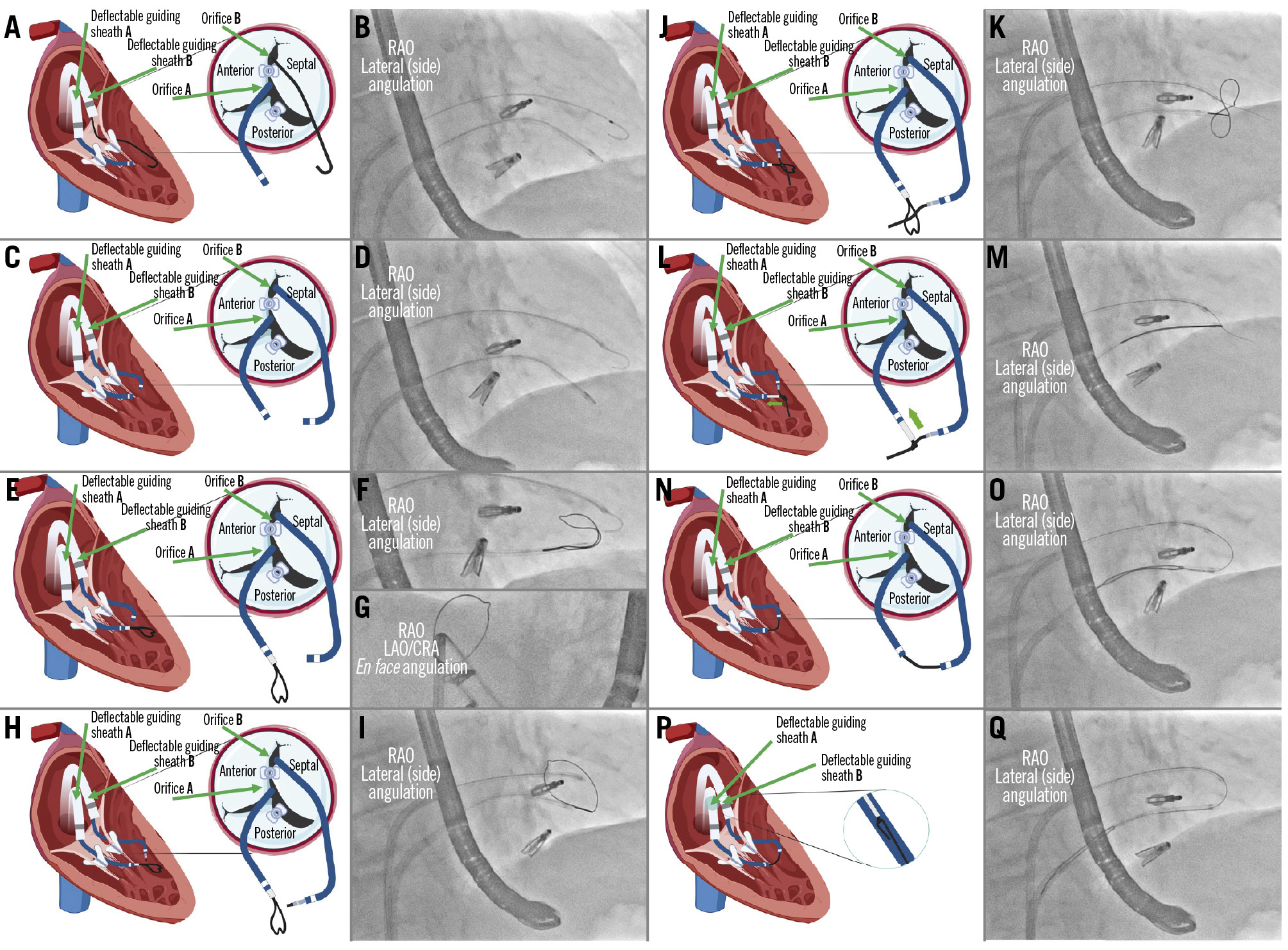
Figure 3. Wire snaring. A) A multipurpose catheter is advanced through orifice “A”; (B) angiographic view of the multipurpose catheter crossing below the upper clip; (C) crossing of orifice “B” using a JR catheter; (D) angiographic view of both catheters after crossing the tricuspid valve; (E) a 20 mm GooseNeck or trilobe snare is advanced through the multipurpose catheter; (F) angiographic view in the lateral (side) angulation showing the snare coming out from the multipurpose catheter; (G) angiographic view in the en face angulation pointing the snare upwards; (H) advancement of a coronary microcatheter through the JR catheter; (I) angiographic view in the lateral (side) angulation with the snare coming out of the multipurpose (lower catheter) and the microcatheter at the tip of the JR catheter (upper catheter); (J) diagram showing the Astato wire crossing the snare; (K) angiographic view of the Astato wire crossing the loop of the snare; (L) snaring and fixation of the Astato wire; (M) angiographic view showing the snaring of the Astato wire; (N) the snared wire is pulled into the multipurpose catheter; (O) angiographic view of the introduction of the Astato wire into the multipurpose catheter; (P) ensure the wire is fixed with the snare and is introduced into the multipurpose wire for more support; (Q) angiographic view of the rail formation after introduction of the Astato wire into the multipurpose catheter. CRA: cranial; JR: Judkins Right; LAO: left anterior oblique; RAO: right anterior oblique
“Flying V” formation
18. Place the microcatheter onto the back end of the Astato wire and bring it close to the Tuohy-Borst rotating haemostatic adaptor, proximal to where the “flying V” will be made. See next step.
19. Focally denude 180o of the Astato guidewire using the sharp side of a scalpel blade for a length of about 2-4 mm (Figure 4A).
20. In the centre of the denuded segment, use the back side of the blade of the scalpel and gently bend it 90o to form the “flying V” shape (Figure 4B). Make sure to softly push the scalpel directly ipsilateral to the denuded part while retracting the wire against the scalpel pressure. That way, the exposed/denuded/non-insulated guidewire is only on the inner surface of the “flying V” that makes contact with the target tissue for laceration. Warning: failure to create a good flying V risks mechanical avulsion, worse haemodynamic instability during the interval between laceration and TTVR, and flapping tissue that might somehow interfere with TTVR anchoring or risk infection.
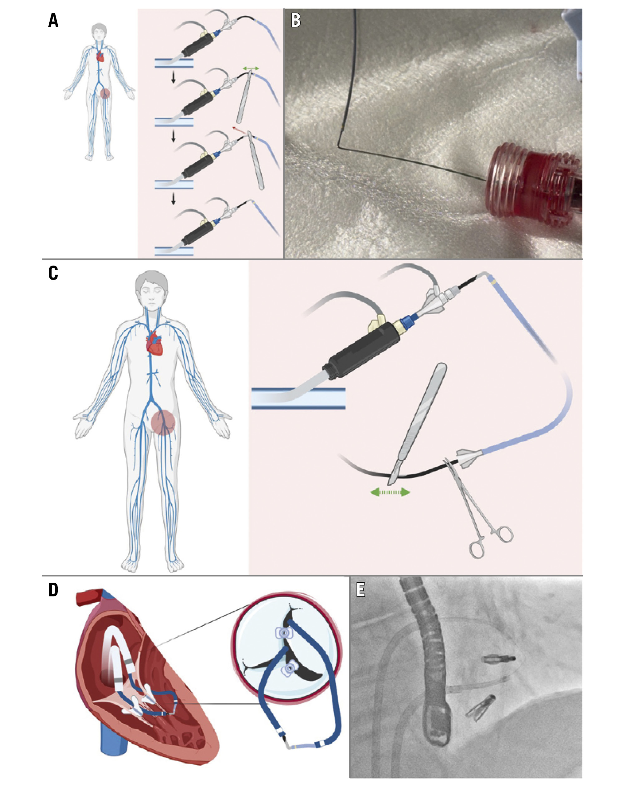
Figure 4. “Flying V” formation and delivery. A) Exposure of a segment of the Astato wire to be denuded with the sharp side of a scalpel blade and bending the segment with the back side of the scalpel blade; (B) final form of the “flying V” after denudation and bending; (C) denudation of the distal part of the Astato wire, which will be connected at its proximal end to the electrosurgery generator – the wire should be fixed with a clamp; (D) visualisation of the “flying V” form after reintroduction of the wire into the body; (E) angiographic view of the “flying V” in position.
“Flying V” delivery
21. Advance the distal end of the microcatheter up to the level of the “flying V” and remove the coating from the distal end of the Astato wire behind the microcatheter using the sharp end of the scalpel (Figure 4C). The radiopaque tip of the microcatheter serves as a fluoroscopic reference to determine the “flying V” location.
22. The distal uncoated part of the Astato wire is used to connect to the electrosurgery generator with an electrosurgery pencil and transmit the energy in a “pure cut” (yellow button). At this step, verify and confirm that the dispersive electrode is attached to the patient’s thigh or flank.
23. Pull the snare catheter from the multipurpose 7 Fr catheter and, at the same time, feed the microcatheter with the Astato wire into the JR4 7 Fr guiding catheter. Make sure to disengage the Y-shaped connector from the 7 Fr JR4 guiding catheter to pull the “flying V” through the Y-shaped connector and reconnect again with the guiding catheter afterwards. Keep the snare loader inside the Tuohy-Borst rotating haemostatic adaptor when retracting the ensnared traversal passage guidewire into the multipurpose catheter, in order to prevent losing ensnarement inside that adaptor. Confirm the wire’s free movement while pulling back using TOE imaging.
24. Lock the microcatheter at its distal end with a mosquito clamp to make sure it does not move backwards (Figure 4C).
25. Once the radiopaque tip of the microcatheter is observed exiting the 7 Fr JR4 catheter, the “flying V” will be located between the 7 Fr JR4 and the 7 Fr multipurpose guiding catheters (Figure 4D, Figure 4E).
Leaflet laceration
26. Check the position of the wire in the lateral (side) and en face projections.
27. Check that the “flying V” crosses through the lateral side of the clip and not through the septal side by using an en face projection (with the wire at the left end of the clip). It is preferable to create SLDA at the septal leaflet, which can be pushed against the septal wall and easily engaged by the anchors of the EVOQUE valve (Edwards Lifesciences) (Figure 5A, Figure 5B).
28. Once the “flying V” of the wire is positioned between the two catheters, maintain a microcatheter tip-to-kink distance of approximately 2 mm (Figure 5C, Figure 5D).
29. Connect the electrosurgery pencil to the distal scraped end of the Astato wire using forceps. Set the electrosurgery generator to “pure cut” mode (yellow button) at approximately 70-100 W (Figure 5E).
30. Connect a bag of dextrose solution to the Y-shaped connector attached to each guiding catheter using a 3-way stopcock and fill a 50 mL syringe connected to 1 port of the stopcock with the solution for each catheter (Figure 5E).
31. Pull both guiding catheters and the externalised guidewire on both sides at the same time while starting manual dextrose flushing/injecting using the 50 mL syringe and delivering energy (yellow button) in the cutting mode (electrosurgery). Use the electrosurgery for no more than 3-5 seconds (Figure 5F-Figure 5H). Avoid common errors: asymmetric traction, which leads to the “flying V” cut being applied unevenly, or worse, the wire becoming covered by surrounding catheters/microcatheters.
32. Repeat the procedure if it is not successful at the first run. Stop the dextrose infusion after turning off the energy.

Figure 5. Leaflet laceration. A) Diagram showing confirmation of the “flying V” in the correct position at the lateral side of the clip to be detached (anterior leaflet); (B) angiographic view in the en face angulation showing the position of the loop at the lateral side of the clip; (C) appropriate microcatheter tip-to-kink distance and position should be maintained; (D) angiographic view in the en face angulation confirming the position of the loop after creating tension by pulling back the catheters; (E) the electrosurgery pencil is connected at the distal denuded part of the Astato wire and fixed with a clamp; the electrosurgery generator is set to “pure cut” mode at 70-100 W; two 50 mL syringes are directly connected to a 3-way stopcock and filled with dextrose solution; (F) while using electrocautery in “cut” mode for 3-5 seconds, both catheters and the externalised wire are pulled back and the dextrose solution is injected simultaneously; (G) confirmation of the “flying V” form in position in the lateral (side) view; (H) angiographic leaflet laceration view after electrocautery is switched off in the lateral (side) view; (I) diagram showing the single leaflet attachment of the clip attached only to the septal leaflet, with the lacerated leaflet (anterior); (J) angiographic view in the lateral (side) angulation showing the remaining loop after laceration; (K) diagram showing the implanted tricuspid valve after leaflet laceration with both clips pushed to the sides of the valve; angiographic views in the lateral (side; L) and en face angulations (M), showing the final fluoroscopic result after tricuspid valve implantation. CRA: cranial; JR: Judkins Right; LAO: left anterior oblique; RAO: right anterior oblique
Leaflet laceration confirmation
33. When leaflet laceration is successful and complete, carefully remove the material, step by step. SLDA can immediately be confirmed by fluoroscopy and TOE (Figure 5I, Figure 5J).
34. Assess the patient’s haemodynamic status and, if necessary, administer intravenous fluids and norepinephrine to maintain a mean arterial pressure of at least 60 mmHg.
35. After leaflet laceration, proceed with standard TTVR according to the patient’s previous evaluation (Figure 5K-Figure 5M).
Conclusions
By following the steps outlined in this paper, operators can streamline the ELASTA-T procedure and facilitate transcatheter tricuspid valve implantation in patients with recurrent tricuspid regurgitation after tricuspid edge-to-edge repair.
Acknowledgements
We would like to thank Dr Robert J. Lederman (Cardiovascular Branch, Division of Intramural Research, National Heart, Lung, and Blood Institute, National Institutes of Health, Bethesda, MD, USA) for his invaluable contribution to the development of this project through his recommendations and clarifications regarding the procedural steps.
Conflict of interest statement
H.A. Alvarez-Covarrubias received lecture fees from SIS Medical AG, LifeTech, and Edwards Lifesciences, not related to the current work. F. Simonetti received lecture fees from Translumina, not related to this work. T. Rheude received lecture fees from AstraZeneca, Abbott, SIS Medical, and Translumina; and a travel grant to the institution from Boston Scientific, not related to this work. E. Xhepa reports lecture fees from AstraZeneca, Boston Scientific, and SIS Medical; and financial support from Abbott, not related to the current work. M. Adam reports personal fees from Abbott, Boston Scientific, Edwards Lifesciences, Haemonetics, JenaValve Technology, Medtronic, and Meril Life Sciences, not related to the current work. M. Joner reports personal fees from Abbott, AlchiMedics S.A.S., AstraZeneca, Biotronik, Medtronic, Recor Medical, Shockwave Medical, TRiCares, and Veryan; grants and personal fees from Boston Scientific, Cardiac Dimensions, and Edwards Lifesciences; and a grant from Infraredx outside the submitted work. The other authors have no conflicts of interest to declare.
Supplementary data
To read the full content of this article, please download the PDF.