Cory:
Unlock Your AI Assistant Now!
A 78-year-old man with stable angina, a positive stress test, and a tight left anterior descending artery (LAD) with a mildly calcified lesion on computed tomography (CT) scan (Moving image 1) was referred for coronary angiography. The angiography confirmed the stenosis, and percutaneous coronary intervention (PCI) of this lesion was proposed.
We analysed the calcium burden with a multimodal approach to plan the intervention and the plaque preparation. After initial angiography (Moving image 2), we performed X-ray-based calcium (Ca2+) mapping through adaptation of the 3DStent technology (3DS; GE HealthCare) to the native vessel1. A deflated 2.0x15 mm PCI balloon was first placed within the target lesion, and a 200° rotational angiography was acquired (Supplementary Figure 1). The data were processed through dedicated software which produced 0.1 mm voxel-based images that were visualised with different standard rendering methods, including a three-dimensional image that was analysable in different projections (Supplementary Figure 1, Moving image 3) and cross-section views (Figure 1A). These images provided two- and three-dimensional representations of the calcifications within the plaque and allowed the relevant assessment of calcium arc radial extension, thickness, and length.
A pre-PCI intravascular ultrasound (IVUS) analysis was performed to confirm plaque composition and to determine stent diameter and length (Moving image 4). The Ca2+ mapping, IVUS, and CT scan images correlated for the calcium radial and longitudinal extents (Figure 1A). The maximal calcium arc radial extent was measured at 270° in the mid-LAD.
In view of these results, 3.0x15 mm non-compliant balloon predilation was performed and followed by 3.0x38 mm everolimus-eluting stent implantation and balloon post-dilation. Final angiography (Moving image 5), 3DS, and IVUS (Moving image 6) analyses revealed a satisfactory result with adequate device expansion and an absence of complications, yet a mild distal myocardial bridge was observed (Figure 1B). The final dose area product was 53.6 Gy·cm2, including 16.6 Gy·cm2 for Ca2+ mapping and 17.0 Gy·cm2 for control 3DStent acquisition.
3DStent technology has been initially developed for post-PCI stent structure and expansion assessment23. Hence, this tool can identify and map any structure with a certain degree of radio-opacity (such as calcium sheets). This case illustrates the correct identification of calcifications within the plaque provided by the tool and the good correlations with intracoronary imaging and CT scan. In addition, Ca2+ mapping proposes three-dimensional reconstruction and therefore allowed in this case an evaluation of the calcium thickness that would not be feasible by IVUS (because of the acoustic shadowing inherent to this ultrasound-based technology). Hence, Ca2+ mapping might represent a new method to evaluate vessel calcium burden before PCI and might thus be an alternative option to intracoronary imaging when the latter is not available.
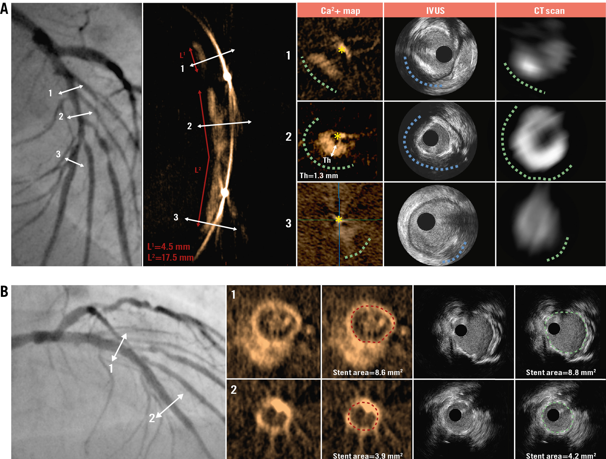
Figure 1. Pre- and post-stenting LAD analysis. A) Multimodal calcium burden analysis in an LAD lesion. The head-to-head comparisons between Ca2+ mapping, IVUS, and CT scan are presented for different cross-sections within the LAD (1, 2 and 3). The X-ray-based methods and IVUS analyses displayed concordant results for calcium radial extent (green dashed lines for Ca2+ mapping and CT scan; blue dashed line for IVUS; yellow asterisk indicates the position of the wire), with a maximal arch of 270° (mid-LAD/section 2). In addition, Ca2+ mapping provided evaluation of calcification thickness and longitudinal extent. B) Post-stenting analysis by 3DStent and IVUS. The head-to-head comparisons between 3DStent and IVUS are presented for the proximal (1) and distal (2) parts of the stent. Each cross-section presents raw images and stent area measurement. Ca2+: calcium; CT: computed tomography; IVUS: intravascular ultrasound; LAD: left anterior descending artery; Th: thickness
Conflict of interest statement
N. Amabile and H. Benamer received consulting fees from GE HealthCare.
Supplementary data
To read the full content of this article, please download the PDF.
Moving image 1. Baseline CT scan.
Moving image 2. Pre-PCI coronary angiography.
Moving image 3. Pre-PCI Ca2+ mapping analysis.
Moving image 4. Pre-PCI IVUS analysis.
Moving image 5. Post-PCI angiography.
Moving image 6. Post-PCI IVUS analysis.